This is my good designs list (for this semester atleast). I'll keep appending to this list every other day so stay tuned. Links have been provided for further reading in order to keep it simple. So here goes.
1. GE90-115B : This mammoth of an airplane engine is the largest in the world.
Good Design features :
a. Unique Complex Swept Fan blade : Made of a composite (carbon fiber and epoxy resin), with leading edges made of titanium to better distribute stresses. Light, durable, less noisy, low rotional speed and exceptional air intake power. Swept back angle leads to better aerodynamic efficiency.
b. Fan Stator Case : Largest part of the engine is fully transportable by air, land or sea.
c. High Efficiency High Pressure Compressor : 9 stage 3D HPC vanes and blades enable a
a thrust of 115,000 pounds. Flow rate and compression ratio (42) has been increased by 20%.
d. Fan Mid-Shaft : Made of a special alloy called GE1014, exclusively developed for this
application enables shaft of older GE90 series design to remain the same, but gives more torque. The alloy has superior fatigue and tensile strength.
e. Hydrocarbon emission levels are 60% lower than those that will be allowed by 2008 standards.
2. Leap Frog Twist and Shout Toys : Toys for children should avoid small parts. It should be intuitive, take into account the child's learning patterns and habits, avoid factors that can bug the parents (like high noise level). It should also be geared towards specific age groups. After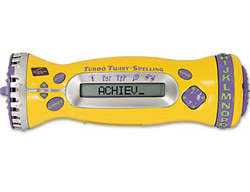 randomly checking the web for children's toys, I came across UK based company Leap Frog. Here's one of their toys - A Hand held Spelling Toy for grades K-5.
Good Design Features :
1. 5 game modes from easy to hard.
2. Twist dial for letter, then slam the end for answer!
3. Teaches core spelling words and fundamental spelling rules
4. Automatically adjusts to player's skill level.
5.Music, animation and sound to keep the child playing.
6. Attractive color, and buttons.
7. Best of all, when the kid has mastered all words in the memory, an additional 1000 words can be added with a Turbo Twist Spelling Cartridge. And its only 20 dollars!
3. Lian Li Computer Case (2oth Memorial Anniversary PC-777A): There have been various mixed feelings from customers, but it looks amazingly cool. Have a look at it. For years, we've been seeing the same old box type desktop cases. Boring as hell. Here's something unusual from Lian Li. I would give it a 80 for aesthetics. It is also quite spacious. This is perhaps a candidate for a bad designs list as well. Since it has a degree of the 'WOW' factor, lets put it here. The space and the snail-like outer body has been irresistable for some buyers.
4. Innovation Factory's IF11000 IceDozer Plus : A bull dozer for ice! Quite the same for the company also. This might be the prayer answered for winter drivers.
1) Features Flexiblade, teeth for breaking into the ice and a front plow.
2) Multi-function innovation brush that features plush and durable bristles to plow the snow. It can be detached, and with its own set of teeth, hard to reach areas can be accessed like car mirrors etc.
3) Attractive, ergonomic handles.
4) Specially designed notch on brush can wipe ice right off windshield wipers.
5. I like the color. Yellow stands out in the snow!
In 2004, this company disappeared. Source : Don Normal.
5. Xerox's Reusable Paper : Its not science fiction. Xerox has experimented on a paper design that can erase itself after a certain time period so it can be used again!!! Embarking on a future concept of "dynamic documents", Xerox produced a chemical that absorbed certain wavelengths of light but then gradually disappeared. While XRCC scientists work on the chemistry of the technology, their counterparts at PARC - the birth place of the laser printer - are working on a device that could write the image onto the special paper.
Good Design Features :
1) Images on the special paper fades gradually in 16-24 hours.
2) Reusable, hence lesser wastage and scraps.
Wednesday, November 29, 2006
2 Good Designs List
Tuesday, November 28, 2006
0 Self Sensing "Smart" Concrete - Part 3
A sample of self sensing concrete (160mm long and 40 mm wide) using the procedures briefed above was prepared for a laboratory experiment. A 3 point testing was done to measure simultaneous compressive/tensile flexular strength and electrical resistivity along the stress line. The results confirmed that flexural strength increased, and sensing ability was achieved. It was also noticed that with different compositions, different results were yielded. The best linearity for fractional change of resistance and strain vs stress was acheived with methylcellulose. In any sensing device, linearity is an attractive feature which makes calibration easy.
The question will arise as to why continuous fibres cannot be used instead of discontinuous ones. One main reason is that it is expensive, and difficult to incorporate into the concrete. The workability is negatively affected, and the same sensing ability is not acheived. Also, it is not necessary to have all that electrical conductivity for making concrete smart.
Another method that could be done for flexural testing is to coat conventional concrete on the tension or compression side with smart concrete. This scheme will yield higher sensitivity on the tension side than on the compression. An implementation of this procedure is coating ceilings of buildings for self sensing behavior. Through out my life, I have noticed cracks on ceilings in concrete that can increase seepage of water. Imagine if you were the victim and the leaking water came from a dirty washroom on the floor above you!
In a real world application as in the levees we talked about, Dr. Chung explained that structural flaw such a micro-crack would increase the resistance of the structure and this change could be continously monitored by probes on the outside of the structure. She also explains that the outside shell of the levee can be made from this composite (similar to what is done in the airline industry nowadays). This will mean reinforcement with sensing capability.
Its an interesting question as tohow small these probes are and what fashion these probes will be placed in. Won't they be subjected to the elements as well? Another question being thrown is whether plants can grow through smart concrete. I've seen tiny plants emerging from regular concrete.
It can be immediately deduced, however, that this sort of technology holds great promises. In situations like earthquakes, or evacuation emergencies in high rise buildings this will greatly help. The weak spots in a structure can be found out without having to actually have a full scale disaster to prove it. A crack is a surface defect and the carbon fibres (impurity) can interfere with the propogation of this flaw, reducing chances of catastrophic failure.
In a post 9/11 world where our borders and important infrastructure (that means a lot economically) are in danger, this technology can provide another avenue of solutions. The idea for this invention adds to other 21st century smart technologies such as cargo analysing at border checkpoints and seaports using magnetic sensors, and "self healing" nano structures.
The 21st century is a dangerous one, as well as one that holds amazing potential for growth in technology. I have to careful about thinking in this manner, but I have often thought that sometimes, disasters are the impulse (the need or want) for newer technologies. In this way, they may be good or bad, but the passion of discovery is never a bad one, whatever may set it off. I'm proud of the fact that Dr. Chung teaches me. I am also confident of the fact that the day is not far when this technology will be adopted in construction after proving to be commercially viable.
1 Self Sensing "Smart" Concrete - Part 2
Self sensing concrete is concrete that is able to sense (measure) its condition without the help of embedded sensors that are used in instrumentation. The patent claim for this invention documents that it is composed of electrically conductive, discontinous, randomly oriented carbon fibres dispersed in an electrically conductive concrete-matrix (or masonsry) base. The electrical conductivity of the fibres are different than that of the base, and as a result of the contact between the fibres and base, the "sensor" attains an electrical conductivity. The concrete acts as the sensor because of this difference in electrical conductivity.
Strain is the change in length of a material per unit length. For ductile materials like steel, aluminium etc, strain is proportional to stress and has a linear relationship until a yield point when strain takes place more easily with a given amount of stress (plastic behaviour). Consequently, the ultimate stress is crossed and the material breaks or ruptures. Concrete on the other hand is a ductile material. Its stress strain curve is almost a straight line without any significant yeield point. What this means is that in the real world, there is no signs or warnings that point to over loading. Hence, concrete structures can fail on a fine morning and will shock many people.
In smart concrete, the detection of strain that can subsequently lead to micro-cracking is done with the help of a slight variation of a scientific phenomenon known as Piezoelectric Effect. Piezoelectric effect is the ability of a material to generate a voltage proportional to an applied stress. In our case, the deciding principle is piezoresitivity, or the proportional change of electrical resistivity with application of strain. In the event of the development of a micro-crack, the contact area between the fibres and the concrete varies sending off a proportionate change in resistivity. This change can then be related to how much strain was encountered.
The change of resistance per unit strain is a quantity called gage factor. Dr. Chung claims that gage factors as high as 700 has been achieved in carbon fibre reinforced concrete.
Traditional methods of sensing were, as we talked about, embedding structures with sensors - peizoelectrics, strain gages, optical fibres etc. This has a significant disadvantage in that the strength of the entire structure can be compromised to an extent because of the heterogenity induced by the cavity. Moreover, surface mounted strain gages are exposed to the elements and can be damaged easily.
In smart concrete, the discontinous fibres in question are about 10-15 micro meters in diameter and nominally 5mm long. Dispersion is brought about through the use of agents such as methylcellulose, silica fume and latex. Preparation includes dissolving the dispersant in water, mixing the defoamer and fibres with this solution and stirring, and then mixing it with concrete, latex and a water reducing agent and they are all mixed in a stone mixer. The mix is then shaken to reduce air bubbles and kept in a mold for some time. After that, it is demolded and cured in room temperature for upto 7 days.
0 Self Sensing "Smart" Concrete - Part 1
Sometime in an earlier post, I briefly described how a professor in my university, Dr. Deborah Chung delivered a lecture on her new invention - smart concrete. I haven't elaborated on what exactly she spoke, and I will do that now.
Dr. Chung is a materials-science scientist and professor at our university. She holds degrees from a number of elite universities in the U.S and has a PhD. I have read a little from her autobiography and I was very impressed and motivated.
Some major disasters around the world mainly happen through engineering failures. Be it man made or natural, a breach in the strength of materials, especially those applied in construction, can mean anything from total collapse of the structure in question to damage to property and loss of human life.
Take for example the levee embankments in New Orleans during Hurricane Katrina. Construction materials were clay deposits interspered with silt or sand seams. It is said that before the flood, the levees themselves had been sinking due to improper sheet metal pilings. They weren't set deep enough. Some of then were only 10 feet deep while others were as deep as 25 feet. Those deep enough could keep the flood at bay than others. With shortage of funds, repairs lagged. I do not know the exact nature of the failure but engineers claim that improper pilings, topping of the huge water surge and erosion of foundational soils were among the main causes of the levee failure. I even watched this on Discovery Channel.
Imagine a situation where the same levees are made of smart concrete that can monitor stress and deformation in real time. You set an acceptable baseline for the deviations. In a situation where the deviation exceeds the limit, an alarm is triggered and engineers are immediately notified.
Or take the situation of a smart roads being able to weigh heavy duty vehicles that move on it, especially at borders or bridges. Think of what that could mean for traffic monitoring and homeland security.
Embedded road sensors have been implemented in areas such as Washington D.C. The Anacostia Freeway that is part of the Interstate 295, has a weight sensor planted under the pavement at the naval station. This helps catch overloaded vehicles that are potentially harming the roads and are a source of tax for the city.
However, a budget of 1 million dollars for a virtual weighing station is too much. This is where smart concrete could come in. Although construction costs with smart concrete could shoot up by 30%, Dr. Chung believes that this option is cheaper than embedding sensors under pavements. At this point in time, it is the high costs that discourages the industry to adopt its use.
Friday, November 24, 2006
Thursday, November 23, 2006
2 Breville Uses NX Based Technology in Juice Fountain
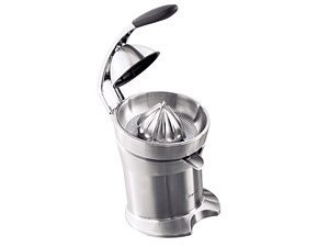
Today, I read a case study about how a top Australian kitchen appliance company named Breville implemented the NX based digital product development process to speed up their product development cycles.
A consistent design innovator and quality setter, Breville had to find new ways to speed up their design process and getting it out to the market. Some of their main issues were :
1. Clay modelled prototypes took weeks to make. Prototype costs were heavy.
2. Design intent was open to incorrect interpretations among the various departments in the company.
3. Long product development cycle.
After the company implemented NX as their design solution, they chose the Juice Fountain product line to streamline with the NX design environment. Not only are the new juicers capable of doing more than conventional models (example, making juices from whole fruit instead of just slices, more raw power for the motor etc) but they also look tremendously attractive to any mom in the kitchen. The new models have generational changes in them compared to the older models, and these have been inspired primarily due to the company listening to the voice of the customer and the data gathered from in house research. We learnt in MAE451 how important listening to customer demands is. From the Kano model, last years demands (the 'exciting' needs that give the WOW factor to consumers) are today's basic needs.
Breville successfully implemented these changes by implementing NX from start to finish. This is perhaps a classic example of a company that retains its traditional methods of design, adopts new technology to lower costs and increase production cycles, and at the same time, adapts to the increasing competition in the market by bringing out new inspired changes in their products.
Wednesday, November 22, 2006
0 Advantages of Solid Modelling
Going from 2D to 3D has many advantages, particularly for companies designing products that require complex manufacturing processes. One such company is Delsey, a France based luggage manufacturer.
Delsey made a wise decision to switch to a 3D modelling application to speed up its product development cycle. Here is the article. It is quite remarkable that products with complex molded surfaces such as straps, zippers and buckles that took 1 to 2.5 years to bring to the market now only took them a matter of 3-4 weeks. Switching to 3D also meant that Delsey could customize parts according to the customer's requirements. They could preserve these changes in a library of models that could be retreived later. The down time and the costs involved with modifications was significantly reduced. The Epoca, a suitcase with built-in wheels for easier transport was made exclusively by a 3d modelling application -UGS's I-DEAS.
Another significant advantage is that standardization of parts speeds design construction and allows the designer to be more creative with his extra time. As discussed in our MAE 451 class, this extra time and resources can help steer the direction towards a better design. This can lower costs and expand performance. The creative technique is an intergral part of the engineering design process.
1 Pulley Assembly
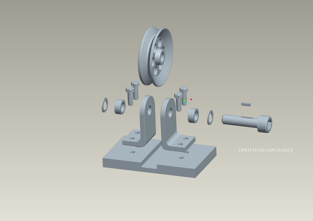
Here's a pulley assembly model done in Pro/E. Given the fact that I followed the book from Dr. Roger Toogood, I took considerable time to make it. I appreciate it that Toogood takes the pain to make the modeller think on his own about certain things, but if he wants to write a book for beginners, he better rethink his style and mode of presentation. I think it can get better in many ways.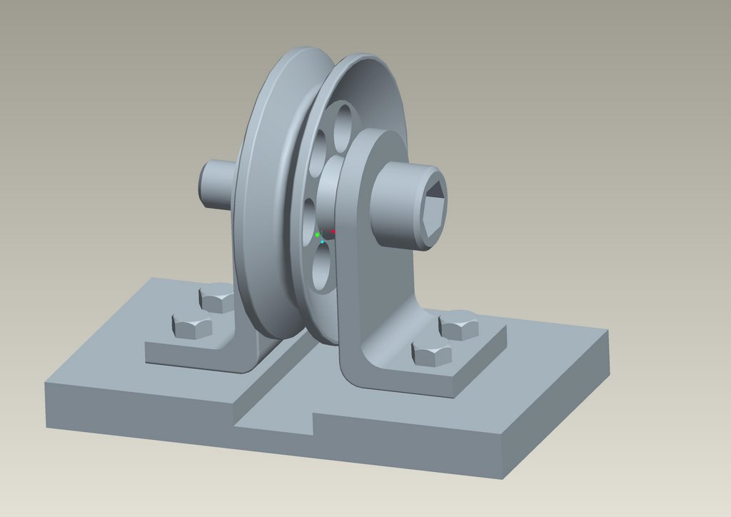
Wednesday, November 08, 2006
0 Yawnnn (design issues...again)
So for two consecutive nights I have been solving fluids problems, playing NFS Carbon, and mulling optimization techniques in engineering design. (Such a waste of time...hehe yeah I know..) The latter is interesting stuff. Considering unconstrainted multivariate optimization problems, does anyone know which method would help one converge fastest to the optimum point? I know it depends upon a lot of things, but you engineers would know...
I'll be starting my design portfolio soon on my blog. Each day, I will write my train of thoughts regarding design methods, things that I find in engineering products around me, and I will also outline my plans to design my final project, which I have yet to confirm with my prof. If I can do it in SolidWorks, that'll be sweet.
Hi to Bosson from China!
Monday, November 06, 2006
0 Max models
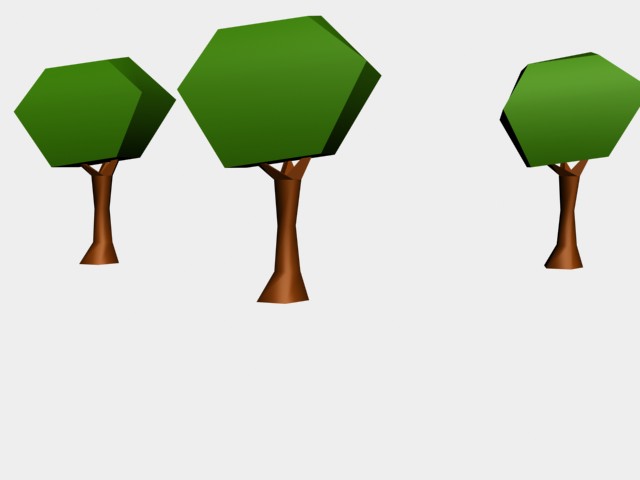

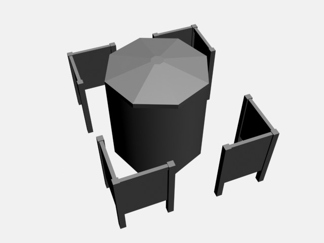
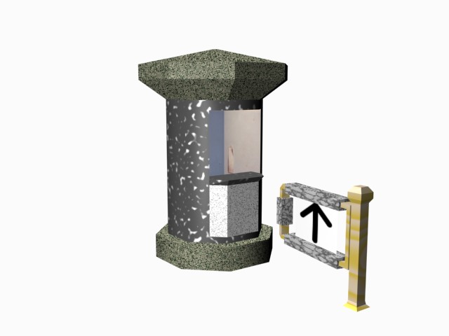
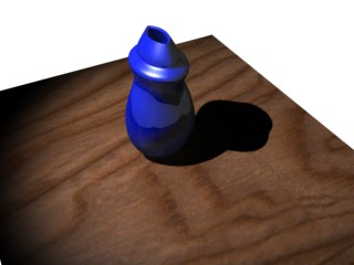
0 More 3ds Max models of mine..

0 ART vs. CAD (Media industry packages vs. CAD applications)
Hello World. Most of you might be wondering where I am. Let me be faithful to you and let you know that I'm terribly busy at school. But its interesting. I'm learning a lot of things.
Last year around this time, I was in the process of learning a 3d modelling tool called Autodesk 3D Studio Max in order to create a 3D world that would be shown on a screen which would eventually be synchronised with a 50,000$ motion simulator at our VR labs. Ofcourse it was only a volunteer experience, but its nice that I got familiar with packages the game industry uses - 3dS, Alias Maya (Alias merged with AutoDesk some months back I heard), and Zbrush.
At this time of the year, I am learning engineering CAD softwares - mainly solidworks and Pro/E. I hope to learn a little bit of them at the same time so that I can know how the same things are done in each of the two applications. I enjoy modelling.
What are the differences between t.v and motion graphics modelling applications and engineering applications? Well, there are a lot of similarities. There is a certain thing such as 'workflow' in all. You start with basic entities and make then more detailed and complicated through the tools each program has. Things like extrusion and revolved cuts are present in both fields (trust me, they make life so much simpler).
However, there is something basic we work with in 3ds Max and other like softwares called Polygons. If you ever played a computer game, you'll know that 3d entities are made up of millions of points, vertices and eventually what it all comes down to is polygons. So in these packages, you're sitting down manipulating polygons to make shapes, sizes, characters, guns, vehicles, cars. The more polygons you have, the more detailed the model will be. Its more like art. Even though everything is done virtually and you don't actually physically touch the model, the way you model itself relates to the actual craftsmanship of the artist. And every computer game or animation film has to optimise its polygon count and detail if considerable rendering time is not to be lost. Rendering is basically making images out of 3d to present it on a 2d platform. Atleast thats what I think it is.
Engineering CAD applications are so much more easier to work with. The way things are made on computer is mostly how things are done in industry - extrusion, sweeping, lathing etc. Welcome to the world of dimensions and mathematical relations, constraints and what not. There's so much intelligence built into the system that so much of your work is simplified for you. Ofcourse, there is such a thing as processing time related to the detail on the model, but none of this is associated with polygons or vertices and such and such. Thats art. (Ofcourse I'm not implying there is no art and creativity in engineering. There is. But the way things are done is different)
This is solid modelling. You create parts, each part has a 'feature' and finally you assemble all the parts to make a working model. Eventually, you'll have to work with the manufacturing division to see how that assembly will be done, but you get the point don't you.
I get it too.
I hope to learn more of solid modelling in the art and engineering side and I also hope to get out some models and animations soon. I like this! You should try it too!
Here are some 3d models from last year, just to give you an idea how much I learnt (modelling, texturing, adding light what not).
0 Headphones

Here's a simple headphone (with a huge strap) made in Pro/E.
By making this model, I learnt about the following :
Variable sweeps, that a curve isn't always necessary to make one (you can even select the edge of a feature to do it) - the headstrap, wire etc were made using this tool.
Solid revolutions with a single profile like the headphones cup
Creating fill patterns like the little holes in the cup
Making polar patterns given an axis (the holes on the headstrap)
Mirroring the whole model - We always want to reduce the amount of our work. So we make one half of the headphones, and mirror it across a given plane to make the other half. That saves us a lot of time.
Modelling time : 4-5 hours (cos I'm a newbie!)
Sunday, November 05, 2006
0 Simple Calculator
Here is a simple calculator model. Surfaces you see are all extruded and the rounded for smoothness. The buttons, the cuts for the mic and speaker have been made using the patterns command. Buttons could have two dimensions (vertically and horizontally) and an offset from a reference line, while the cuts for the speaker had just direction.
More detail could be added to this model by selecting the buttons as drawing planes and drawing numbers and finally extruding them a given height.
Time : 1 1/2-2 hours (I'm a beginner afterall!)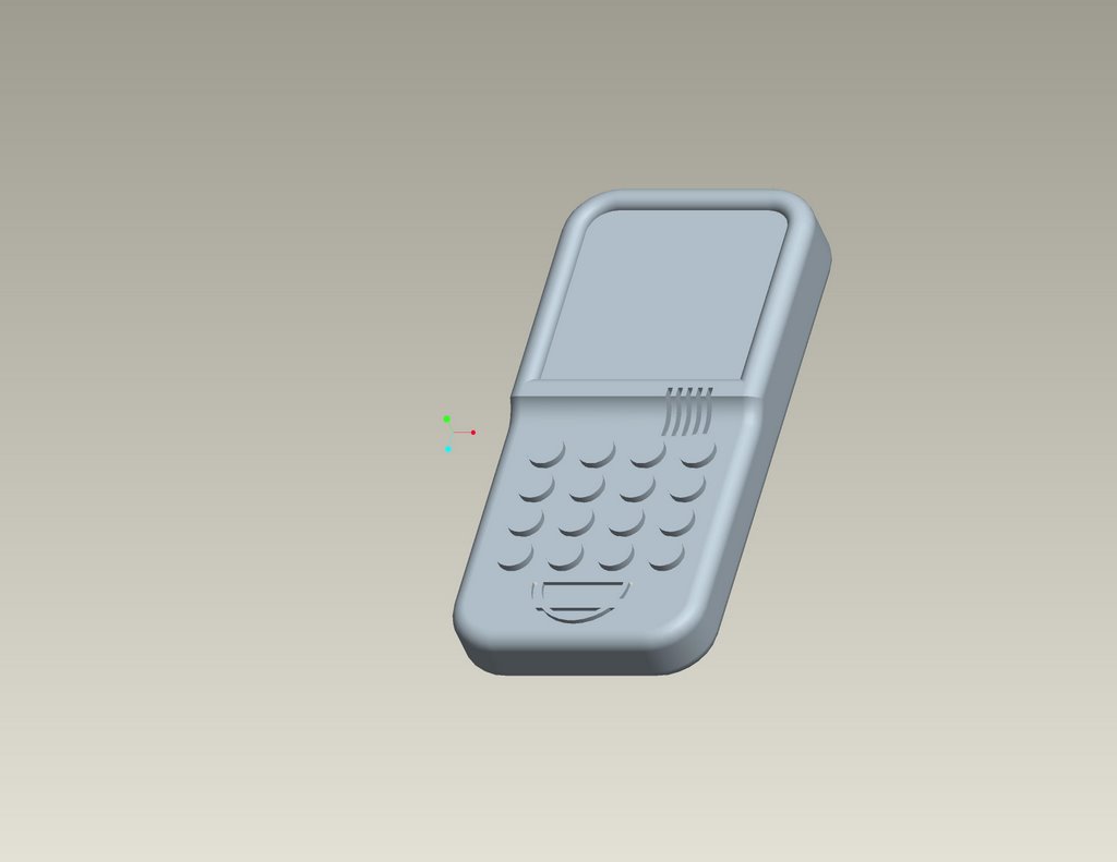
Done in Pro/E


